History
In 2006, grundutbildningen at the Physics department of Lund University (called UDIF back then) wanted a remote control system to facilitate the setup of their Lasershow for the public.
At that time I worked with electronics development at the department of Elementary particle physics (which later became High Energy Physics and today it’s called Division of Particle and Nuclear Physics).
UDIF contacted us and asked if we could develop this for them which we did.
The system consists of three parts: The switch keyboard, the master transmitter and the slave receiver.
Of course a firmware is required for the processors to actually do something!
Both the processors for the master and slave are still available for purchase, although they are ‘mature’ product. (Meaning that they will be available for a long while but it’s not recommended to develop new products using them since they have been superseded with better and cheaper processors.)
The system allows for 128 units (7-bits) to be addressed and 7-bit data is then transmitted to those units.
The license free 868MHz band is used with a UART protocol. The transmitter is an ER900TS and the receiver module is an ER900RS, both obsolete 20 years later.

The switch control panel has 8 sections of 12 flip-switches. Each position of a switch sends out a unique remote-control code.
The function of the master is to scan the keyboard and send the key switch code to the receiver. The receiver then activates or deactivates a relay and some voltages. The only extra feature available at the master is the ability to manually send address and data through its DB-9 serial port.
One rather nasty setup of the original master unit is that the keyboard switch functionality has to be programmed into the processor. It can be done through the serial port but it’s quite cumbersome.
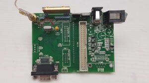
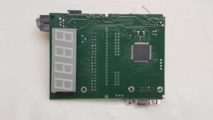
We never got around to find a case to build it into so it has been operated like that for 20 years!
During those years I have learnt that a board should be designed to fit into a specific enclosure, never the other way around!
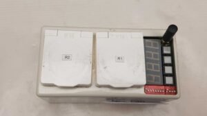
This is the box that is distributed throughout the location where the show will be held.
It has a built-in power supply capable of delivering a switchable 5V 1A, 3.3V 1A and a non-switchable 12V 1A.
Two 230V relays control 2 individual outlets, but unfortunately at the time it was decided that those share the control with the 3.3V so that when sending a specific data, both the relay and 3.3V triggers at the same time.
There is an 8-bit DIP-switch allowing the address of the unit to be set and an additional 4-bit DIP-switch for some other generic display setting like switching off the display. Additionally there are also 4 push buttons that were never fully implemented.
Approximately 40-50 slave units were built and no more can be built because of the unavailability of the receiver module.
One common fault of the broken slave was that the receiver module had given up. Luckily there was a small number of the ER900TRS transceiver module available at Farnell, so I bought 10 of them which was half their stock so we now have some left for future repairs. The ER900TRS is a superset of ER900TS and ER900RS since it can both transmit and receive (which probably wouldn’t be separate units today) and extra lucky is that it is actually pin compatible with the receiver, so a swap is trivial.
2026 upgrade
In June 2026 I was asked if I could service some of the receivers that had broken during those 20 years of service. I also got the master unit so that I could test the receivers.
For obvious reasons the slave units can’t be upgraded (I need access to all), but only 2 master units exist so that’s a different story. It’s also the unit in most need of an upgrade – so I gave it one!
First of all the hardware got an update with a modern processor which costs a fraction of the original processor, yet delivers more features in this application, an AVR128DA64. The master is now housed in a professional enclosure with custom made front and back panels.
A new user interface has been added with a rotary select knob, a play button, a stop button, a separate RGB status LED and a USB-micro port for programming and PC communication.
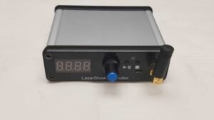
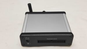
The original hardware required a DC-adapter for power but the new master can run on that same DC-adapter as well as the power from the USB-port. It should also be noted that the new hardware does not require a keyboard attached, it will still function with most of its features intact.
The new implemented firmware functions are as follows:
4 modes, normal mode (shows SEnd), macro mode (shows PGn), playback mode (Pb.x) and record mode (rEc.x)
Normal mode is the only mode available on the old hardware where the display shows what is being sent (address/data).
The new features available are the following:
- Normal mode – use knob and buttons to send any address/data combination
- Macro mode – any key can be reprogrammed to any address/data directly from the front panel (single macro, this replaces the ‘program keyboard’ functionality of the old keyboard)
- Macro mode – any key can hold a sequence of max 16 keys (multiple macro) and each key has two positions, each capable of its own macro. Worth noticing that reprogrammed keys are used as their new function but multi macro keys keep their original non-programmed function. A key can only be reprogrammed or macro-programmed, not both.
- Playback mode – any of 10 program sequences can be played back, rotate the knob to select slot. White LED indicates empty slot, red LED is occupied
- Record mode – selects between 10 slots in either key mode (records hardware key switches) or HF mode (see below), LED indication is the same as in playback mode. Allows a command sequence to be recorded into 1 of 10 program memory slots. Each slot can hold up to 3000 key flips during a maximum of 6553.5 s or about 1 hour 49 minutes with a time resolution of 0.1s.
- Record HF mode – records actual traffic, not key switches. That means a key with a macro recorded functions as a macro sequence, not as a separate key. Any incoming RF traffic is also recorded so ‘eavesdropping’ on a show from the old master can be recorded into memory.
Exactly how the unit operates is described in the master user manual.
The PC communication has also been updated to support bulk upload and download to allow offline editing of the device memory.
A python script is supplied to allow exporting and importing data from an excel file where the timeline can be edited.
Schematic, firmware, manuals and tools are available for this project.
Design-files, production files and library parts for PADS Professional are available on request.
After assembling, testing and debugging the new master, I realized that although it’s a much more complete unit, it’s greatly hampered by the fact that it can only ever serve the existing receivers. No new receivers can ever be added. In order to rectify this drawback I made a version 2 of the master.
Lasershow master version 2
Based on everything learnt from designing and testing version 1 of the master unit, version 2 was designed with the specific intent of adding a second RF module that can support new slave units. The new RF module is a RC1180-RC232 which is a more modern transceiver which is readily available, cheaper and more capable than the ER900 series modules. One directly notable change for our design is that in the same setup, it supports the full 256 (8-bit) address and data space whereas the ER900 only supported 128 (7-bit) address and data.
Master version 2 has both modules and therefore supports ALL slave units, old as well as new.
It can send the full 8bit address and data over the RC1180-RC232 module but only the supported 7-bit address/data is transmitted using the ER900 module so it supersedes all previous masters with full backward compatibility.
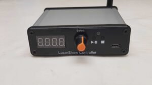
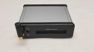
Apart from the full address/data range, there are currently no other additional features in the firmware for version 2.
Lasershow Slave unit version 1
Version 1 slave units differ from the old slaves in several different features
- No internal power supply, requires external power supply
- Only supports RC1180-RC232 communication
- 2x 230V power relays (data 0x90/0x91 for relay 1, 0x92/0x93 for relay 2)
- 1 settable power output (0-5V in 0.1V steps, 0-1A settable with potentiometer) (data range 0xA0-0xD2)
- 16 digital outputs (outputs 0-15, data range 0xE0-0xEF) or
- 8 digital outputs (outputs 0-7, data range 0xE0-0xE7) and 8 digital inputs (inputs 0-7)
- 8 DIP-switches for device address, 4 DIP-switches for additional functionality
The output or output/input feature is selected using DIP-switch 2/4 on the front.
(Note that the 4 additional DIP-switches are only read on boot, not while running)
Inputs are a new very flexible feature, if the slave has base address 0x’address’, a pulse on input 0 will transmit the code address 0x’address+1′ data 0xE0, i.e. it will trigger output 0 on the next address. Similarly, input 1-7 triggers outputs 1-7 in the next unit.
For extra flexibility, by setting dipswitch 3/4 the sent code is not 0x’address+1’/0xE[0-7], instead the address/data stored in memory is sent.
The memory can be manipulated using the terminal to set any address/data per input.
An example would be to use input 0 to send 0x’address’/0x90 and input 1 0x’address’/0x91 – i.e. activate/deactivate its own relay 1.
The inputs are edge-triggered and not debounced so they must be wired correctly to avoid false triggering.
The idea behind the inputs is that the slaves themselves can control a sequence of event without the master doing anything apart from setting the ball rolling. Even though an external event only can trigger the transmission of one code per input, there’s nothing stopping several inputs to be connected in parallel. Only the imagination limits how advanced a setup can become.
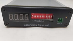
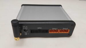
From a manufacturing point-of-view, the new generation slave is much simpler to assemble. That means a lower the cost compared to the previous generation. Custom-made slave units can easily be developed because of the generic construction of the slave so additional or alternate features can be easily added, just contact me if you have such needs.
Firmware and software
All firmware and software development has been created with the help of Claude AI. If you want to change any of the software but aren’t too familiar with C++ or Python, load the markdown files (.md files, available in the firmware zip) into an AI chat and let the AI help you to alter the source code.
Start the session with something like ‘Hi, can you read the markdown files and familiarize yourself with the project?’
Programming
The firmware should be compiled in Arduino IDE with DxCore installed and the AVR128DA64 MCU selected (DA family)
Also select ‘Wire->2 Wire’ mode (any of them) and ‘SerialUPDI – Normal: 230400’ programmer option.
Open the box and move the jumpers on J2 onto the alternate position to program the MCU.
Move them back to the current position for communicating with the MCU.
The USB port uses a CH340 USB-to-serial bridge and should be recognized as such in Windows.
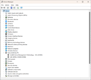
However, with some bad luck it can be hijacked as a Braille reader under a LinUSB device.
If it’s identified like that, download the correct driver from https://www.wch-ic.com/downloads/CH341SER_ZIP.html , uninstall LinUSB and then install the correct driver.
Editing
A set of tools are supplied which can bulk upload or download the device memory from the master.
The script is written in python and requires pyserial for the communication and openpyxl for excel import/Export.
Python is installed by default on most if not all Linux distributions but not in Windows.
If you don’t already have it, get the latest windows install at https://www.python.org/downloads/windows.
That should install the python interpreter as well as the pip script. Make sure to add Python to your PATH variable.
Open a command window and install the tools with ‘pip install pyserial’ and ‘pip install openpyxl’
When python, pyserial, openpyxl and the com port works, open a command window to where you unpacked all lasershow tools and write ‘python lasershow.py --help’ to see how to use it.
If all program slots and macros of the master are used, the transfer can take a couple of minutes at the most but it is usually quicker than that.
Once a show has been downloaded, the excel-file can be directly edited with regards to timeline, address and data.
Note the use of an optional alias file which will help identify which device belongs to which address.
It’s only used as a visual aid in Excel and never exported or stored in the master.
The alias file has to be created manually, so only a template is supplied.
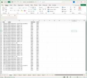
There is also a timing.json file which adjusts the timing of the master to real time (adjusts for drift). Use the correct timing for the correct master, however if you’re just interested in editing the commands and don’t care about the timing, just see to it that you use the same timing-file (default) for download & upload.
Use the same lasershow.py script to upload the edited excel-file back to the master and it becomes available as a playback program.
Worth noticing is that the upload will overwrite entire device memory, i.e. every slot is erased and then written with new data so nothing not specifically mentioned in the upload is deleted.