GBox

How we work

0
More than 30 years of experience

Although there’s nothing wrong with open-source or cheap layout software, would you really want to mount a $5000 FPGA on a $10000 PCB developed on a free layout tool with limited support?
Well we wouldn’t, which is why we use Mentor Graphics PADS Professional suite to do all our development.

Our experience developing board layouts began more than 30 years ago using Mentor Graphics Board Station for 15 years followed by Expedition Enterprise for another 15 years and today we are running PADS Professional. Don’t let the name fool you, PADS Professional is the same software as Expedition but for an individual rather than for an enterprise.

Highlights from our design flow:

Our Schematics are drawn in PADS Professional Designer.

Design simulation is performed using PADS AMS which is a mixed-signal simulator capable of SPICE and VHDL-A modelling.

The tools supports a combination of simulations with electrical, magnetic, mechanical, thermal and hydraulic simulations.

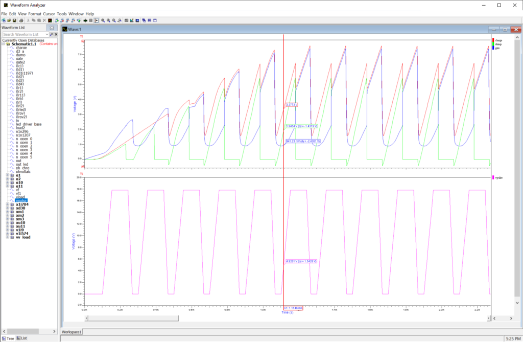
A model wizard helps to create custom models including mixed-mode models. Simulation results can easily be viewed in the Waveform Analyzer which allows advanced waveform manipulation.

PADS Library Manager tool is where all symbols, cells (=footprints) and parts are created and stored into a single central library.
A good design requires a good library.

The Layout editor is where all part placement, routing, layout editing occurs. The final stage is always to produce manufacturing output.
Many designs require either assembly panels (an empty frame used during assembly and discarded afterwards) or manufacturing panels where multiple design instances are put into a single frame. The layout tool supports both types of panels.

Professional 2D drawings of e.g. board or front-panels can easily be created within the tool removing the need of having a 3rd party creating mechanical drawings for simpler items.

Extensive design rules checking (DRC) can be performed on the layout where all aspects of the design are checked. Design for fabrication (DFF) also allows to check the manufacturability of the design to reduce the layout changes necessitated by manufacturer feedback.

The tool also gives a 3D rendering of the board assembly which is a great way of checking the footprints. The fidelity of the result depends on the parts model quality.

3D DRC is also supported.
3D pdf and step-model of the board can easily be exported.

Our experience of VHDL and FPGA programming is similarly long and advanced. We’ve mostly used Lattice’s MachXO2/3 as board controllers for smaller designs and Xilinx’ Virtex for larger designs. Yes, we have designed boards and developed VHDL code for Xilinx’ largest FPGAs!

Our design experience covers sensitive amplifier boards sitting inside the world’s largest particle detector as well as FPGA platforms costing as much as a new car.
We offer unbeatable knowledge of how to design boards interfacing Synopsys’ HAPS systems and we also have our own range of HAPS compatible accessories